


AOI, Automated Optical Inspection for Pin Fault Detection
Abstract
Automated Optical Inspection replaces the error-prone backplane testing with high-precision fault detection. By combining computer vision with optics, AOI identifies any bent, missing or misaligned pins that oftentimes pass standard electrical tests but fail in the field.The result: up to 10-100x faster fault detection, almost no false negatives, and accuracy that’s sub-millimeter.
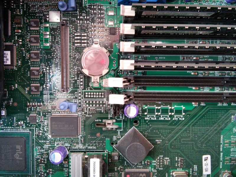
Backplanes are a group of electrical connectors with pins that are positioned parallel to each other in a way where each connector pin is linked to the corresponding pin of all the other connectors, forming a computer bus. Backplanes ensure correct interconnection, performance, and reliability of the system.
Each backplane can have 60 connectors and each connector can number 200 pins. So, in order to guarantee a needed backplane quality before it leaves a factory, a thorough product inspection is crucial.
However, doing backplane testing manually is a repetitive and error-prone job, and it requires a lot of time to manually pick, place and press each connector, which in turn increases the manufacturing cost. As a result, the companies are looking to implement automated inspection software, in particular, Automated Optical Inspection (AOI) systems are becoming the quality control method of choice.
Traditional Approach to Automatic Pin Fault Detection in Backplanes
As we said before, inspection is one of the most critical areas of the press operation. Highly accurate backplane fault detection became a very real and growing problem for the industry. The industry needs an automatic production test method for backplane that is fully scalable to deal with large samples. Some backplanes now have over 100,000 connector pins on them.
Regardless of the type of Pin deformation (crushed, bent, broken off, smashed, etc), the primary concern is a connection that may pass an open/short electrical test but fail subsequently in the field due to either loss of signal integrity or the connection opening up. This can occur if the pin shorts to the top of the barrel and passes the electrical test.
Here is a list of backplane fault detection technologies:
- Optical AOI
- True Position Datum
- X-Ray
- Programming
- Electrical Test
- Bed of Nails
- High Node Count RQD
- Expensive Fixturing
- Need Detection Automation
Crushed and bent pins, while they may, in some cases, pass continuity tests, cannot be detected by traditional test methods, such as X-Ray, manual visual inspection, Electrical Tests, etc.
Today, we will cover the AOI, its challenges and suggest a complex solution that allows drastically improve the faulty pin detection efficiency for bent, missing, or dispositioned press-fit pins.
What is AOI and its main challenges
There are many press-fit problems that would not be detected using a contact resistance measurement but would still represent a huge connection loss on a multi-gigabit per second digital signal. Automated optical inspection (AOI) is an automated visual inspection of any printed circuit board that allows detecting most of the backplanes faults, including fatal failure (e.g. missing pins) and quality defects (e.g. bent pins, pins in an incorrect position) using a camera to scan the board.
Using Automated Optical Inspection technology produces good results in terms of process and quality improvements.
Challenges of backplane testing
Meeting the combined challenges of high digital transmission speed, and high channel density interconnection has dramatically changed backplane connectors from relatively sturdy 2mm pitch assemblies to fragile 1.2mm and smaller pitch assemblies. These modern connector types are much more prone to having a defect.
Key press-fit pin connector challenges include:
- Smaller – Shorter Compliant Press Fit Pins
- Lower Pin insertion / retention forces
- Smaller pitch spacing
- Smaller PTH FHS
- Higher Pins quantity per inch/cm
- Higher speeds
- Higher Power Options
AOI Testing Methodology
Automated optical inspection system has the simple pattern matching algorithm at its core, which limits the backplanes faults detection range, and decreases AOI efficiency. Each time the camera scans the backplane, it produces a set video frames that are used for pin fault detection. The way it works is that the AOI performs optical recognition of the actual pin tip position and compares it to the theoretical pin tip position from the modeled template. The test passes if the recognized position of the pin is within the specified range and fails if the pin has not been found in the region of interest (ROI) at all or was detected outside of the specified range.
The pin fault detection is done in three testing stages, each coming after the previous test passed:
- We determine ROI around the expected pin location.
- Then we need to calculate the average position of pins by analyzing pins location in the connector and build a grid.
- We perform pattern matching on ROI by calculating the best match (%).
AOI testing challenges
The pattern matching algorithm provided a pretty good level of detection, however, it depends strongly on the quality of the video frames obtained with the camera that is lowered by each of these factors, listed below:
- Illumination
Lighting conditions influence the quality of pattern matching and should be controlled and calibrated with RGB normalization. - Shadows and other noise in image frames
In the case where pins are near the shell of a connector, they get natural shadows, which distorts the image frame. Here we cannot use the same template as for pins situated in the center of the сonnector. Pin models are created manually by extracting portions of the image with 1-pixel accuracy. - Large number of complex templates
Each pattern matching has to run through every possible model. A large number of templates increase the test time. - Different types of connectors
There are a lot of connectors that can be used the same way, however, they are never identical visually. - Pin Variation
The same company can produce a number of different pin variations.
How to improve pin fault detection using AOI
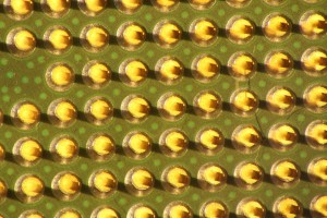
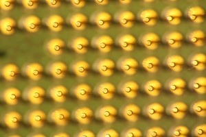
Automatic pin fault detection in backplanes is becoming more time- and cost-consuming. Our R&D team suggests a new approach to checking connector pin depths on high-speed nets in backplanes. For image acquisition system our computer vision engineers suggest using camera lenses with short depth of field. In optics, particularly as it relates to film and photography, depth of field (DOF), also called focus range or effective focus range, is the distance between the nearest and farthest objects in a scene that appears acceptably sharp in an image. Although a lens can precisely focus at only one distance at a time, the decrease in sharpness is gradual on each side of the focused distance, so that within the DOF, the unsharpness is imperceptible under normal viewing conditions.
If the distance from the camera to test samples is fixed, we can focus our lenses on pins tops. In that case, the scene behind the pins tops and in front of them should be blurred. It can be a good solution for hardware recognition assistance.
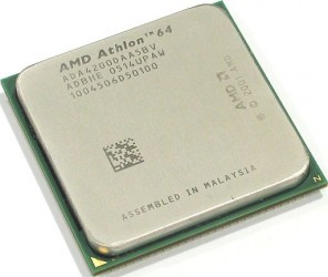
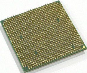
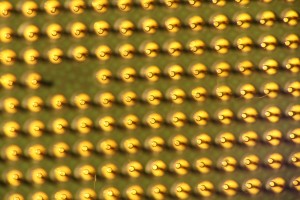
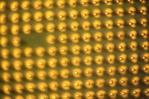
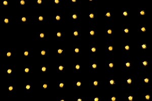
Object on photos – AMD Athlon 64 CPU: CPU pin length – 2mm, distance between pins – ~1.28mm
IMG1. The common view of pins of CPU. Setup settings v1.
IMG2. Photo of CPU pins where pin tops are in focus. Setup settings v1.
IMG3. The common view of pins of CPU. Setup settings v2.
IMG4. Photo of CPU pins where pin tops are in focus. Setup settings v2.
The best result is obtained when processing image IMG2.
All photos have a size of 5184×3456 pixels.
Results
Due to the nature of the pattern matching and affecting factors, current system’s bent pin recognition rate varies for different types of pins. Our solution allowed eliminating most of the limitations of standard AOI. We got the following results:
- Improved inspection equipment capabilities by implementing a different type of camera lenses.
- The universal algorithm that does not depend on image resolution.
- The solution can be used to detect a fault in any types of pins.
- High processing speed up to 10-100 times depending on the connector density.
- False negative rate: 99.9%.
- High accuracy of pin position detection up to 0,1%mm.
To know more how our AOI solution can be applied to your business case, contact us.