Computer vision companion module for stabilized UAV hover
Project summary
The solution is a companion computer that integrates with existing aerial systems for stabilized UAV hovering. The common GNSS denial & intrusion, complex terrain & occlusion, and other mission blockers are eliminated.
Stable positioning with an up to 8° drift and angles of an up to 25° tilt.
Services:
Project overview
In modern conflict zones, GPS jamming and spoofing are common methods making GNSS systems less reliable. A solution to resolve this challenge: a complementary FPV module for autonomous position maintenance even in GNSS-denied environments.
We introduced computer vision, visual odometry, and other advanced techniques to enable stable hovering. This allows FPV drones to function without continuous manual stabilization, even without GNSS connection.
A unique, warfare-connected ecosystem of services
Each feature is validated with soldiers in combat, not sanitized lab conditions, to deliver battle-ready systems that minimize the risk and defeat the enemy.
Equip, deploy, and win – choose technology repeatedly validated in real military scenarios.
Main goals
- Achieve autonomous FPV hovering in challenging, GNSS-denied environments
- Free operators from frequent manual corrections while maintaining yaw control
- Provide a stable platform for extended aerial operations
Steady hover, clear footage, safer soldiers
Get evidence, protect men
How the solution works
The module integrates seamlessly with existing FPV systems by using these components:
- Single board computer (SBC) running custom Linux image
- Downward-facing camera
- Betaflight and ArduPilot compatible software interface
How the solution works:
- At the target location, the pilot can activate the autonomous position hold
- The module will maintain the drone’s exact position and altitude by leveraging:
– IMU readings from the flight controller
– CV algorithm to track captured features - The computed control commands are sent to the flight controller to maintain stable hover
- The pilot can adjust the yaw while hovering by using the switch on the remote controller, for example, to change the direction of the attached transmitter
Key applications
- Surveillance operations
- GNSS-denied missions
- Remote control signal retransmission
- Anti-jamming applications
Key features
Firmware integration
- Betaflight via MSP protocol
- ArduPilot via MAVLink protocol
Stabilized hover
- Position and altitude hold even without GNSS coverage
- Yaw adjustment while maintaining position hold
Real-time onboard data processing
- ARM-based SBC with custom Linux OS
- Computer vision and control logic execution
Sensor fusion
- Camera-based odometry combined with IMU data
- Image stabilization to compensate for tilt and rotation
Modular and scalable architecture
- Plug-and-play compatibility (7 inches and larger)
- Easy adaptability to different firmware and hardware configurations
Our contribution
R&D (research & development)
- Proof-of-concept development, which included:
– comprehensive hardware analysis
– systematic parameter optimization - Computer vision algorithm development following thorough competitor analysis
A thorough competitor analysis to ensure market-leading performance.
Software development
- Custom algorithms with robust software architecture
- Protocol-level engineering to integrate Betaflight and ArduPilot platforms
That means maximum flexibility across different drone platforms and unique, mission-centered requirements.
Hardware & industrial design
- Meticulous selection of optimal companion components, balancing performance and cost:
– single board computers (SBC)
– different-type cameras
– D/A converters - Thought-out design of a ruggedized enclosure for harsh military environments
Field trials
- Continuous maintenance protocol establishment to ensure:
– ready-to-deploy status
– indoor testing
– rapid debugging - Field trials conducted across variable conditions to validate achieved performance
Main challenges
Advanced control
More robust PID controllers were developed, better optimized for each driving axis (pitch, roll, yaw, throttle). With extensive field testing, this enabled platform-specific calibration that compensates for characteristics including configurations and drone component variations.
Multi-firmware compatibility
We addressed the complexities of working with different flight controllers and mastered according protocols. Our solution was designed to combine Betaflight’s and ArduPilot capabilities to enable seamless operation across platforms.
1. Betaflight integration
Betaflight firmware was chosen as the target platform, as it’s the leading flight controller to run various crafts. Being designed primarily for manual-only operation, its autonomous flight capabilities are limited, in particular to accommodate our objectives.
The challenge was handled by developing a better-fitting, custom algorithm for autonomous flight control.
2. ArduPilot integration
ArduPilot firmware was selected as the target platform to extend compatibility beyond manual-only operation. It provides multiple autonomous flight modes in standard GNSS environments, thereby providing a foundation for advanced flight control.
To leverage ArduPilot’s capabilities:
- by replacing MSP with MAVLink communication
- And applied a feature to emulate the sensor by using visual data instead of GPS data
Angle stabilization
A software-based gimbal system that stabilizes visual streams during dynamic flight conditions was developed. As drones are tilting and shifting to retain their position, the system automatically compensates for distortion, thus ensuring consistent tracking no matter the weather.
Altitude management
An altitude estimation algorithm was implemented by integrating visual odometry and drone barometer data. The algorithm can interpret camera movement and prevent visual shifts from causing potential dispositioning, thus ensuring hover stability.
Real-time performance
With the computing power of the single board computer (SBC), real-time performance is a massive challenge. But nonetheless, it’s critical to have a fast (and low-latency) control loop when operating high-speed drones.
This challenge was addressed through careful software optimization and multithreading.
Limited sensors
We aimed to keep the module as affordable as possible, so the only available options were:
- The built-in inertial measurement unit (IMU), which isn’t very accurate, and barometer
- And a downward-facing camera
Computer vision to extract additional information from the integrated camera was leveraged to achieve robust control under these limiting conditions.
Robustness despite weather changes
Wind and luminance adaptability
Important corrections within hardware and algorithms were implemented to mitigate wind speed & direction. Image preprocessing has helped to negate changing luminance, which complicated target aiming and tracking.
This way, the solution works reliably beyond controlled, ideal conditions.
Oscillation leveling
Even when the drone is holding its position, it can start wobbling when affected by sudden weather changes. This drives energy consumption and may also interfere with the other equipment.
The problem was solved through careful PID tuning and proper weight distribution.
Feature matching
The algorithm is leveraging visual odometry that uses feature matching and estimates up-to-date movements. The location is calculated by integrating odometry displacement over periods (between pairs of frames).
We resolve the challenge by addressing several aspects:
- to match the frame with the last updated key frame
- The camera is tuned to obtain video footage of the best-possible quality
- What’s more, there were some experiments with combinations to select:
– keypoint detectors
– feature descriptors
Stable hover and oversight despite sabotage
Close gaps, preserve assets Tools and technology stack
- C++
- Python
- Linux
- Bash
- ROS Noetic
- SDL2 X11
- OpenCV
- ORB
- SURF
- Gazebo
- Betaflight SITL
- ArduPilot SITL
- MSP
- MAVLink
Timeline:
- 2 months – R&D phase
- 4 months – software development and testing
- Total duration: 6 months
Team:
- 1 project manager
- 2 C/C++ developers
- 1 Python developer
- 1 computer vision engineer
- 1 control systems engineer
- 1 hardware engineer
- 1 DevOps specialist
Value delivered to business
- Mission success in contested field conditions
The module, with autonomous position and altitude hold, will function even under GNSS and EW interference, which ensures reliable performance in challenging, GPS-denied environments.
- Operational resilience
The module was designed to deliver stable performance even under quickly changing weather conditions – wind speed and direction, different-intensity luminance, as well as precipitation.
- Balanced workload in high-risk field scenarios
The solution frees operators from continuous manual corrections, thereby allowing more focus on priorities – target identification and observation, ground coordination, and others.
- Rapid integration into existing military drones
The solution was designed already compatible across platforms without requiring hardware modifications.
Technical specifications
Module weight | 200 grams |
| FPV compatibility |
|
| Platform examples |
|
| Firmware compatibility |
|
| GNSS independence | GNSS independent thanks to:
|
| Functional scope | An autonomous position and altitude hold |
| Remote control jamming resistance | Once autonomous position hold is enabled, the drone will maintain stable hover no matter remote control signal integrity |
| Wind resistance | Up to 12 m/s (may depend on drone platform capability) |
| Hold accuracy | Stable position with an up to 8° drift in moderate wind conditions |
| Tilt tolerance | Supports pitch/roll angles of up to 25° tilt |
| Working range |
|
| Core components |
|
| Data processing |
|
| Image stabilization | Software-based stabilization to compensate for movement |
| Control integration |
|
| Module deployment | Field-ready enclosure |
Field trials
During trials, the drone has maintained stable hover for over 20 minutes under the following conditions:
- 17 °C (air temperature)
- 5 m/s (wind speed)
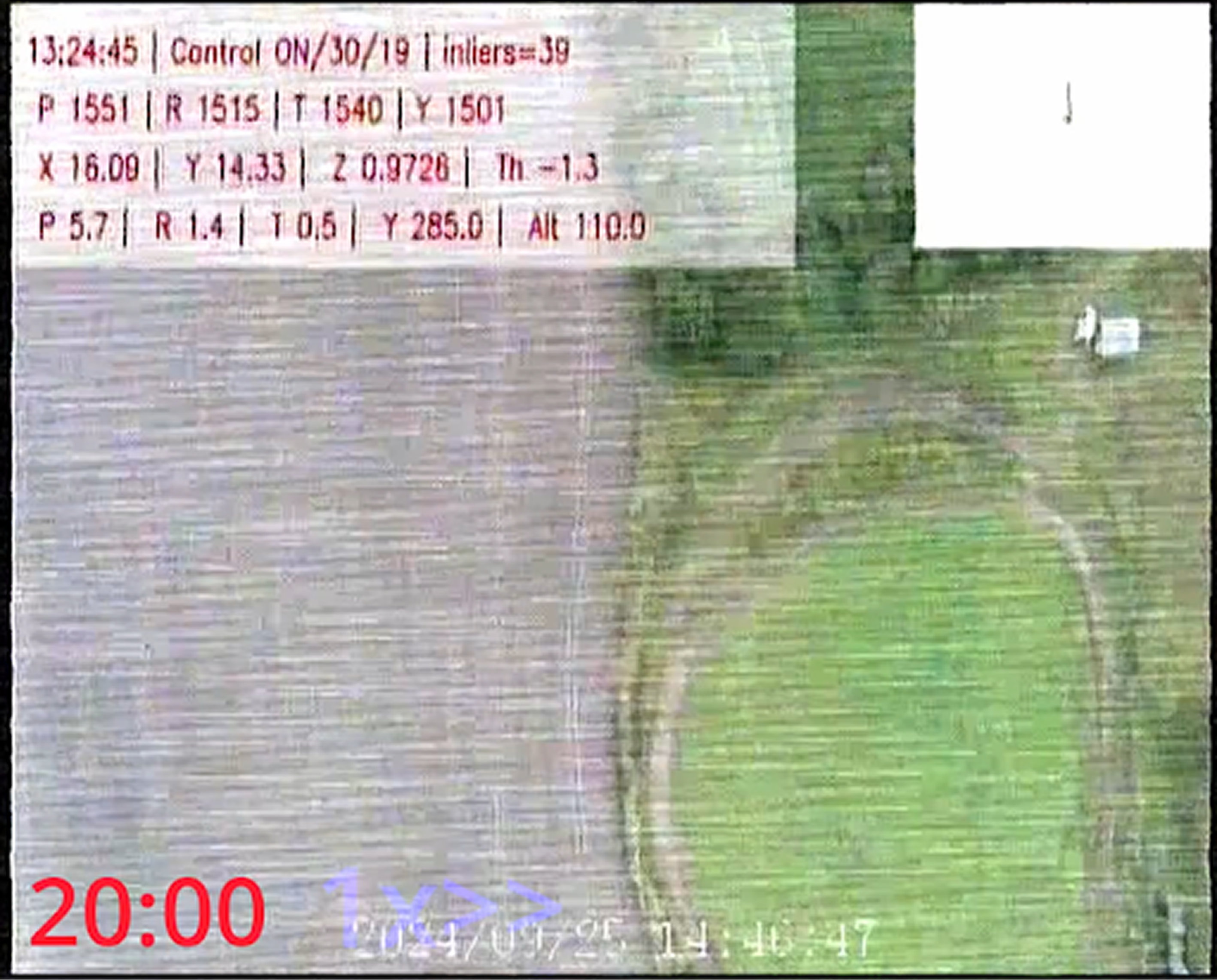
The top-left section displays real-time telemetry from the flight controller and the visual odometry (VO) system and highlights how these values change during hover.
The top-right section presents a map that tracks the drone’s exact position when hovering:
- In an ideal environment, the path would appear as a single point and indicate a perfectly stable hold
- In practice, it might slightly drift when affected by changing wind and lighting conditions (the system continuously compensates for deviations to keep the drone as close as possible to its intended position)