Signal processing. Extracting useful features from electric signal

Signal processing is an enabling technology that encompasses the fundamental theory, applications, algorithms, and implementations of processing or transferring information contained in many different physical, symbolic, or abstract formats broadly designated as signals.
Signal processing uses mathematical, statistical, computational, heuristic, and linguistic representations, formalisms, and techniques for representation, modeling, analysis, synthesis, discovery, recovery, sensing, acquisition, extraction, learning, security, or forensics. In this article, we would like to show extracting of a useful feature from signal got from linear CCD in Laser triangulation sensor.
How signals are gathered
Laser triangulation sensors are used for accurate distance measurement. They are named as such, because the sensor enclosure, the emitted laser, and the reflected laser light form a triangle.
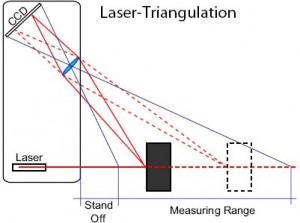
The laser beam is projected from the instrument and is reflected from a target surface to a collection lens. The lens focuses an image of the spot on a linear array camera. The position of the spot image on the pixels of the camera is then processed to determine the distance to the target. The beam is viewed from one side so that the apparent location of the spot changes with the distance to the target.
Pixelized array detectors are referred to as digital detectors, not in the sense of 0s and 1s but rather because their output is composed of discrete voltages representing the amount of light on each element of the detector. A 1024-element detector consists of 1024 discrete samples that constitute the output signal see figure below.
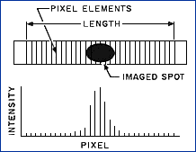
Pixelized array detectors produce a series of digital outputs that vary depending on the amount of light detected by each element of the array.
From the description above, you can see that the spot on the linear CCD is not an ideal dot. Because of optical distortions we got a blurry spot on the sensor. The main goal is to get beam spot linear coordinate with very high accuracy.
On the image below you can see the real signal from linear CCD.
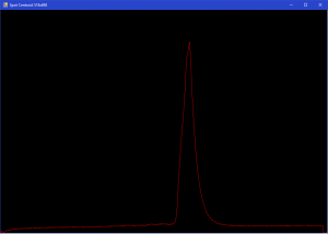
To compute spot coordinates, we use centroid calculation. But every CCD sensor has optical and background electrical noises which cause distortions of the output digital signal. This leads to lower quality computing of centroid. To put it simply, the spot centroid coordinate has some deviation.
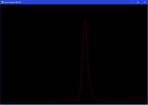
To increase accuracy first of all we need to remove background noise. For this purpose, we can use median filtration or Fourier filtration. See pictures below:
Median filter with frame 5:
Frequency analysis and Fourier filtration:
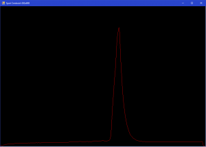
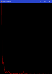
Both of these methods are acceptable. Fourier filtration gives a little bit better result but it is a more time-consuming operation.
After signal noise reduction it is a good idea to analyze histogram and remove constant background:

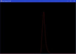
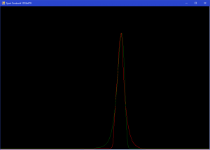
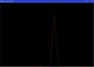
As result, we got more or less cleared signal without background. But these noises also impact our signal shape which leads to centroid calculation deviation. To solve this problem, it was decided to calculate an approximate signal with a close mathematical function that follows the signal shape. The variables for this function, in this case, were chosen as points of chart edges on determined height and maximum signal value.
The results of approximation on different signal levels, please see below:
Approximation on signal level 1/e:
Approximation on signal level 1/e^2:
Also, it is possible to foresee manual approximation for automatic approximation accuracy calculation:
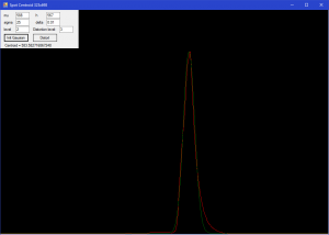
Described above method of signal processing and extraction of useful information by mathematical approximation gives very promising results. It all depends on the hardware and chosen mathematical function. In our case, we got an accuracy increase by a few hundred times vs rough signal.
